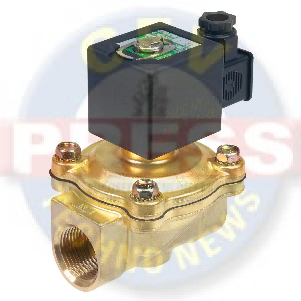
SOLENOID VALVES-ALL YOU NEED TO KNOW
A solenoid valve is an on/off electromechanically operated valve which consists of an electromagnetic actuator (solenoid) and a valve body. The solenoid-plunger assembly is the valve actuator responsible for opening and closing the valve. This actuator can be arranged in such a way that the plunger action can either open or close only. There is no intermediate, or in-between position, so there is no way for a solenoid to throttle flow. The valve body consists of the pressure containing parts in-contact with the process fluid.
The solenoid converts electrical energy into a mechanical pull/push action. This consists of a coil of wire tightly wrapped around an iron core, and a ferromagnetic plug or plunger. Components vary depending on the design. As an electrical current passes through the coil, a magnetic field is generated. The magnetic field lines can be imagined as a series of circles with the direction of its current axis. In the case of a flowing current along a looped coil, the circles combine forming the magnetic field
Different technologies of solenoid valves
There are 3 main different technologies; Direct acting, In-direct acting and Forced-lift piston type.
- Direct-acting valves require no differential pressure to remain in their rest state and in the NC version, they will only allow flow once energized. These valves are very robust and can be used in a process line for simple isolation purposes of for safety purposes. The can also be used on the outlet to a tank where sometimes pressure can get very low but the valve needs to remain open.
- In-direct acting valves require a pressure differential across the inlet and outlet to allow them to stay in their rest state. For example if a valve was normally open and there was not a large enough pressure differential, the valve could be intermittent and possibly close if inlet pressure dropped too low. These valves should only be used if pressure levels are within the parameters specified in the datasheet and IOM instructions.
- Forced-lift valves are used in high pressure applications where neither of the above valve types can deal with the higher pressure processes such as 40 Bar plus. This valve uses a much bigger and higher power coil to open or close and the seat of the valve is directly connected to the bottom of the piston/plunger assembly eliminating the need for a diaphragm.
Solenoid Valve Components
- Coil
The coil is one of the main parts of the solenoid which consists of an insulated copper wire wound tightly around a core tube. As described earlier, a magnetic field is generated when current is applied.
- Core
The core, also referred to as the armature or plunger, is the moving part of a solenoid. This is a soft magnetic metal; soft, meaning a ferromagnetic metal that can easily be magnetized and demagnetized at low magnetic fields. When the coil is energized generating a magnetic field, the core is attracted which opens or closes the valve.
- Core Spring
The core spring returns the core to its original position when the magnetic field is removed. The core spring design and configuration in the solenoid assembly varies depending on the valve operation. In some designs, such as the latching type solenoid valves, it does not use springs to create a return action.
- Fixed core
This is installed at the closed end of the core tube which also improves the magnetic flux. The material is also a soft magnetic metal.
- Diaphragm
The diaphragm is a flexible material that isolates the solenoid assembly from the fluid. The diaphragm is designed to contain the pressure of the fluid.
- Stem
The stem is part of the valve where the core or plunger is attached. As the core is attracted by the coil, the stem moves along with it actuating the valve.
- Disc
The disc blocks the flow of fluid when the valve is closed. In some solenoid valve designs, diaphragms, bellows or pinch devices are used instead of a disc to block fluid flow. Depending on the application, the disc is usually made of corrosion and erosion resistant materials such as PTFE or stainless steel.
- Core Tube
The core tube is where the coil is wound. This also acts as a soft magnetic core which improves the magnetic flux generated by the coil.
- Seat
The seat is the orifice that presses against the disc when closing the valve. Like the disc, the seat may not be present depending on the valve design. The seat is also made of corrosion and erosion resistant material. Once the seat or disc is damaged, the valve will become passing and unable to stop flow.
- Seal
The seal, like the diaphragm, isolates the solenoid assembly and the external environment from the fluid. Depending on the application and the process fluid, there is a variety of seal materials available such as PTFE, FKM, NBR and EPDM.
- Bonnet
The valve bonnet seats at the top of the valve body. The core tube and stem extend through the bonnet and into the valve.
- Body
The body is the main part of the valve which holds the diaphragm, disc, seat and the inlet and outlet ports.
- Bleed Orifice
For indirect or semi-direct acting solenoid valves, a bleed orifice is installed on the diaphragm. Some valve designs use an equalizing hole. The bleed orifice enables the valve to use the line pressure to open or close the valve.
- Pilot Channel
For indirect acting solenoid valves, a pilot channel is included into the valve body. This is where fluid flows from the top of the diaphragm and into the downstream side of the valve.

